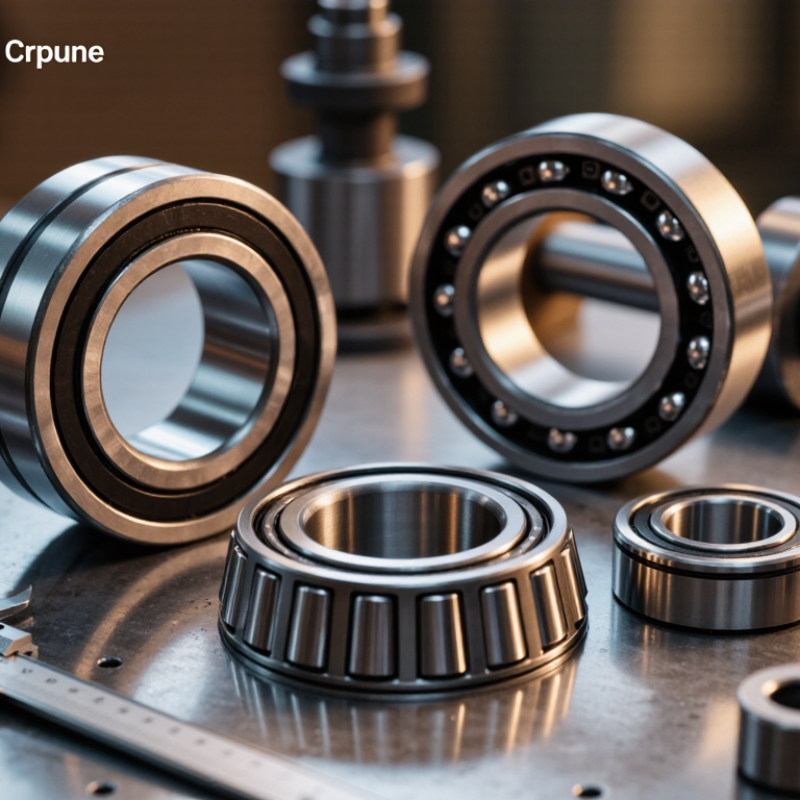
Choosing custom machining for non-standard bearings begins with the application, not the drawing. A bearing may face unusual loads, limited space, high temperature, corrosion, or constant vibration. These conditions determine the raceway geometry, material, hardness, clearance, seal design, and surface finish. Non-Standard Bearings Custom Machining must therefore connect engineering calculations with real operating details.
Dr. Tedric A. Harris, author of Rolling Bearing Analysis, offered a practical warning: “Bearing performance depends on the complete operating system, not the bearing alone.” This principle remains valuable. A machined ring can look flawless under inspection, yet fail early because of poor lubrication, shaft misalignment, or excessive preload. The surrounding assembly matters.
Experienced manufacturers usually review load direction, rotational speed, shaft fit, housing tolerance, lubricant type, duty cycle, and contamination risks. They may request a sample shaft, a worn bearing, or operating photographs. These physical details often reveal problems that a two-dimensional drawing hides. Material selection also deserves attention. Stainless steel may resist moisture, while hardened bearing steel can provide better fatigue performance under demanding loads.
There is no universal machining recipe. That is the uncomfortable part. A tighter tolerance is not automatically better, and a cheaper material may create costly downtime. Engineers should compare prototype results with calculated expectations. Dimensional inspection, hardness testing, runout checks, and controlled trial operation improve confidence.
The best supplier asks difficult questions. They explain trade-offs clearly. More importantly, they document what remains uncertain. Reliable Non-Standard Bearings Custom Machining is not merely about producing an unusual shape. It is about creating a dependable bearing system for a clearly understood purpose.
Custom machining should begin with three measurable conditions: load, speed, and environment. ISO 281:2007 defines L10 life as the life reached by 90% of identical bearings. Its calculation uses L10 = (C/P)p million revolutions Here, C is dynamic load rating, P is equivalent load, and p equals 3 for ball bearings or 10/3 for roller bearings. The number looks precise. Real machines are less polite.
In practice, I record radial and axial loads separately, then check shock loads during startup. A bearing carrying 2,000 N at 1,800 rpm behaves differently from one carrying the same load at 300 rpm. Temperature, dust, moisture, lubricant viscosity, and shaft misalignment also matter. ISO 281 offers a strong baseline, but its basic equation cannot fully describe contamination or installation errors. ISO 15243 helps classify damage, including wear, corrosion, and surface fatigue. My early estimates often ignored mounting distortion. That was a costly lesson.
Tips: Provide the machinist with load charts, speed ranges, housing dimensions, shaft tolerances, and operating temperatures. Specify surface finish and fit requirements clearly. Ask for inspection records, not only a drawing. For harsh environments, consider sealing, corrosion-resistant materials, and lubricant compatibility. Calculate L10 in revolutions, then convert it into operating hours. Check both normal and peak conditions. One overlooked shock can invalidate an otherwise careful design.
Custom machining for non-standard bearings begins with the ISO 76 static load requirement, not the drawing alone. ISO 76:2006 defines the basic static load rating through permanent contact deformation. The reference limit is approximately 0.0001 times the rolling element diameter at the most heavily loaded contact. This small number matters. A 20 mm ball allows only about 2 micrometres of deformation.
Material selection should match the load, speed, environment, and section thickness. Through-hardened chromium bearing steel commonly reaches 58–64 HRC after quenching and tempering, as reported in ASM Handbook, Volume 4: Heat Treating. Its high hardness supports strong raceway contact resistance. For humid or chemically exposed equipment, martensitic stainless steel can improve corrosion resistance. However, its lower achievable hardness may reduce static load capacity. That trade-off is often underestimated.
Heat treatment must control distortion before final grinding. A practical route includes vacuum hardening, sub-zero treatment when suitable, and tempering near the specified dimensional range. Retained austenite can change dimensions later. ISO 76 does not prescribe a universal safety factor, so engineers often apply 1.2 to 1.5 based on shock and uncertainty. That is engineering judgment, not a fixed rule.
In my experience, machining tolerance is sometimes blamed too quickly; uneven hardness or poor support during inspection may be the real cause. A hardness map and post-treatment roundness check provide more reliable evidence than one surface reading. (ISO 76:2006; ASM Handbook, Volume 4)
Choosing custom machining for non-standard bearings begins with the fit, not the drawing. ISO 286-1 defines the tolerance system, while ISO 286-2 provides deviation tables for shafts and housings. For a 50 mm nominal diameter, an IT6 tolerance is approximately 16 micrometres. That small range can change mounting force, preload, and service life. A rotating inner ring often needs an interference fit, such as k5 or m5, while a stationary outer ring may use H7. These are starting points, not automatic answers.
Load direction, speed, temperature, and material strength must be checked together. A 2023 industrial maintenance survey published by Plant Engineering reported that unplanned downtime commonly costs manufacturers thousands of dollars per hour. Poor fit selection can create fretting, ring creep, or excessive heat before failure becomes visible. In practice, I would record the actual shaft diameter at several points, inspect roundness, and account for thermal growth. I have seen drawings that met the grade but failed in operation. The drawing was correct. The assumptions were not.
Tips: Specify the nominal size, ISO fit, IT grade, surface roughness, roundness, and measurement temperature. Confirm whether the bearing ring rotates relative to the load. Ask the machinist to report actual measured values, not only pass-or-fail results. For thin housings or aluminum parts, consider operating clearance and thermal expansion before selecting H7. A trial assembly is often cheaper than correcting a seized bearing.
| Machining Decision | Operating Condition | Recommended Shaft Fit | Recommended Housing Fit | Typical ISO 286 Grade | Typical Starting Tolerance at 50 mm Nominal Size | Engineering Reason |
|---|---|---|---|---|---|---|
| Fit Selection for Bearing Rings | ||||||
| Light radial load with a rotating inner ring | Low speed, low vibration, low risk of ring creep, and frequent disassembly | h6 or j5 | H7 | IT5 to IT7 | Shaft h6: approximately −16 to 0 µm Housing H7: 0 to +25 µm |
A relatively light shaft fit simplifies assembly and removal. Confirm that the load is not sufficient to cause inner-ring creep. |
| Normal radial load with a rotating inner ring | General machinery, moderate speed, steady radial loading | j5, j6, or k6 | H7 or J7 | IT5 to IT7 | Use the ISO 286-2 limit-deviation table for the selected fit; the exact limits depend on the nominal diameter range. | A transition or light-interference shaft fit helps prevent ring creep while limiting bearing internal-clearance reduction. |
| Heavy radial load or reversing load | High load, shock, vibration, or a load direction that changes relative to the ring | k6, m6, or n6 | J7, K7, or M7 | IT6 to IT7 | Calculate the actual interference from ISO 286 deviations and verify the remaining bearing clearance. | Greater interference reduces the risk of ring creep, but excessive interference can reduce radial clearance and increase operating temperature. |
| High-precision rotating assembly | Low runout, controlled preload, precision spindle, inspection equipment, or high rotational accuracy | j5 or k5 | H6 or J6 | IT5 to IT6 | Use a calibrated measurement process and ISO 286-2 deviations for the exact diameter range. | Tighter dimensional grades improve location accuracy, but they do not by themselves define total bearing runout or preload. |
| Stationary outer ring under a stable load | Outer ring load direction remains fixed relative to the housing | j6 or k6 | H7 | IT6 to IT7 | Housing H7 at 50 mm: approximately 0 to +25 µm | A standard housing location fit may be sufficient when the outer ring is not exposed to circumferential loading or creep. |
| Outer ring exposed to rotating or circumferential load | Load direction rotates relative to the outer ring, or the ring is likely to creep in the housing | j6 or k6 | J7, K7, or M7 | IT6 to IT7 | Determine the housing interference from ISO 286-2 and verify housing distortion limits. | A tighter housing fit can prevent outer-ring creep, but thin housings may deform the bearing raceway if interference is excessive. |
| Axial locating side of a bearing arrangement | One ring must provide accurate axial location while the opposite ring must accommodate thermal expansion | Locating side: j5/k5 Floating side: h6 or j6 |
Locating side: J6/K6 Floating side: H7 |
IT5 to IT7 | Specify the axial shoulder, abutment, and clearance separately from the radial fit. | Only one bearing location should normally control axial expansion unless the design intentionally uses preload or a fixed bearing arrangement. |
| Custom Machining Tolerances for Shaft and Housing Seats | ||||||
| Shaft bearing seat diameter | Standard precision bearing seat | ISO 286-1 / ISO 286-2 fit code | Not applicable | IT5, IT6, or IT7 | At 50 mm, IT6 is approximately 16 µm and IT7 is approximately 25 µm for the relevant ISO diameter range. | Choose the grade according to load, speed, required runout, assembly method, and bearing clearance class. |
| Housing bearing seat diameter | Machined bore for a standard outer ring | Not applicable | H6, H7, J7, K7, or M7 | IT6 or IT7 | At 50 mm, H7 is approximately 0 to +25 µm. | Housing material, wall thickness, temperature, and ring load determine whether a clearance, transition, or interference fit is appropriate. |
| Shaft shoulder diameter and height | Axial support for the inner ring | Use a shoulder diameter larger than the bearing inner-ring abutment diameter | Not applicable | Design-specific | Specify the shoulder diameter from the bearing geometry drawing; do not choose it from the shaft fit alone. | Provide a reliable axial seat without interfering with seals, cages, chamfers, or bearing corner radii. |
| Housing shoulder diameter and height | Axial support for the outer ring | Not applicable | Use a shoulder diameter smaller than the bearing outer-ring abutment diameter | Design-specific | Maintain clearance from the bearing chamfer and corner radius. | The shoulder must fully support the outer ring while avoiding contact with non-load-bearing chamfer areas. |
| Shaft seat cylindricity | Precision or high-speed rotation | Typically no looser than the selected diameter tolerance unless otherwise justified | Not applicable | Use a drawing-specific geometric tolerance | A practical starting value is 30% to 50% of the diameter tolerance for demanding assemblies. | Excessive cylindricity error can create localized interference, alter bearing clearance, and increase vibration. |
| Housing seat cylindricity | Thin-wall housing or high sensitivity to raceway distortion | Not applicable | Use a drawing-specific geometric tolerance | Use a controlled geometric tolerance | A practical starting value is 30% to 50% of the housing diameter tolerance for precision assemblies. | Housing form error can distort the outer ring and produce raceway waviness, noise, or uneven load distribution. |
| Coaxiality or total runout between two bearing seats | Two-bearing shaft or housing arrangement | Control relative runout to the functional datum | Control relative runout to the functional datum | Design-specific | Use a value based on bearing span, speed, allowable misalignment, and required runout. | Relative alignment between seats is often more important than the individual diameter tolerance. |
| Surface roughness of shaft bearing seat | Interference or transition fit | Typically Ra 0.4 to 0.8 µm | Not applicable | Surface requirement | Specify the measurement direction and filtering method when the fit is critical. | A controlled surface reduces fretting, improves contact consistency, and makes the achieved interference more predictable. |
| Surface roughness of housing bearing seat | Standard machined housing bore | Not applicable | Typically Ra 0.8 to 1.6 µm | Surface requirement | Use a finer finish for precision or high-speed assemblies when justified by testing. | Surface texture affects seating, friction, fretting resistance, and the effective fit after assembly. |
| ISO 286 Fit and Grade Rules for Design Documentation | ||||||
| Fit designation format | Use a complete ISO fit code on the machining drawing | Lowercase letter + grade, such as k6 | Uppercase letter + grade, such as H7 | ISO 286 | Example: shaft k6 with housing H7 | Lowercase letters identify shaft tolerance zones; uppercase letters identify hole or housing tolerance zones. |
| Nominal diameter dependency | Any custom bearing seat | Always use the actual nominal diameter and the applicable ISO diameter step | ISO 286-1 and ISO 286-2 | Do not copy a micrometre value from a different diameter range. | Fundamental deviations and IT values vary with the nominal diameter range, so the same fit code can have different absolute limits. | |
| Bearing internal clearance check | Any transition or interference fit | Verify the fit against the bearing's initial radial internal clearance | Bearing-specific calculation | Include interference, shaft and housing material, operating temperature, load, speed, and lubrication. | ISO 286 defines mating-part limits; it does not guarantee the final bearing clearance, preload, or operating temperature. | |
| Temperature compensation | Large temperature difference between shaft, bearing ring, and housing | Recalculate the effective fit at operating temperature | Thermal expansion calculation | Use the thermal expansion coefficients of the actual materials and the expected temperature range. | Different expansion rates can convert a clearance fit into interference or reduce an intended interference fit during operation. | |
| Inspection method | Critical non-standard bearing components | Measure diameter, roundness, cylindricity, runout, and surface finish with calibrated equipment | Drawing-specific inspection plan | Measure at multiple angular and axial positions under controlled temperature. | One-point measurement cannot reliably verify form error or the functional fit of a precision bearing seat. | |
| Important design note | The fit recommendations are engineering starting points, not universal substitutes for a bearing manufacturer's internal-clearance, load, speed, temperature, and mounting analysis. Final shaft and housing limits should be calculated from the exact nominal diameter, bearing ring load, material, operating temperature, assembly method, and required service life. | |||||
Non-standard bearings rarely fail because the drawing looks unusual. They fail when the chosen process cannot hold the working geometry. CNC machining suits prototypes and complex outer profiles, especially when material removal is moderate. A machinist can adjust tool paths quickly. Bore size, flange thickness, and mounting holes remain easy to inspect. CNC may leave tool marks, though. Those marks can affect seals or lubricant flow.
Grinding becomes stronger when raceways, bores, or shoulders require tight size and low roughness. It removes little material, so stock allowance matters. A practical workflow machines the blank first, then grinds functional surfaces after heat treatment. In production, this often improves repeatability. However, grinding can create heat damage when coolant delivery is poor. Check surface texture, roundness, and hardness near the raceway, not only diameter.
EDM is useful for hardened steel, narrow slots, and profiles that cutting tools cannot reach. Wire EDM can produce sharp internal shapes without large cutting forces. Sinker EDM handles recessed forms, but electrode wear may change small details. It is slower and needs careful flushing control. Choose the process from load, speed, lubrication, and inspection requirements. Experience helps, but assumptions still cause mistakes. I would confirm the datum strategy and run a sample part before approving quantity. A drawing can hide distortion, and measurement must not be an afterthought.
Choose CNC, grinding, or EDM according to the required bearing geometry, dimensional accuracy, surface finish, material, and production volume.
The chart uses a practical 1–5 engineering suitability scale: 1 = limited suitability and 5 = strong suitability. CNC machining is flexible for complex prototypes and low-to-medium volumes, grinding is preferred for tight tolerances and superior raceway finishes, while EDM is useful for intricate profiles in electrically conductive hardened materials.
When choosing custom machining for non-standard bearings, verify the basic envelope against ISO 15:2017. This standard defines boundary dimensions, including bore diameter, outside diameter, and bearing width. It does not define every surface-finish or runout limit. That distinction matters. A machined ring can match the ISO 15 envelope and still create vibration during operation.
Use a calibrated micrometer and a coordinate measuring machine for dimensions. Measure at a controlled temperature near 20°C, as ISO 1:2016 establishes this reference condition. Check radial and axial runout against the drawing, then record the actual values, not only pass or fail results. ISO 492:2014 provides tolerance principles for rolling-bearing dimensions and rotation accuracy. For surface texture, use ISO 21920-2:2021 parameters, such as Ra, Rz, and the assessment length. A typical ground raceway may require an Ra near 0.2–0.4 μm, but the correct value depends on load, speed, lubrication, and contact design.
Ask the machining supplier for inspection records, instrument calibration dates, and sampling plans. ISO 281:2007 shows why geometry affects bearing rating life, although it cannot predict every field failure. In practice, I have seen acceptable dimensions hide waviness on a raceway. The report looked complete.
Do not rely on appearance alone. Recheck datum selection, thermal drift, and clamping distortion. Small errors remain possible. That is where engineering review becomes essential.